Wiring Diagram Sensor Led Light - Motion Sensor Wiring Diagram | Wiring Diagram - Connect the leds to pin 3 of the arduino.. If not, the structure will not function as it ought to be. Whether you must use a 4pdt switch or another switch in your pcb, altium designer can provide help. It shows the components of the how to wire motion sensor light diagram beautiful patio post lights flood light wiring diagram uk led instructions pir motion sensor motion sensor. Find this and other arduino tutorials on arduinogetstarted.com. ··· wiring diagram 400w pir led motion sensor 100w energy approval high brightness ip65 powerful outdoor solar flood light.
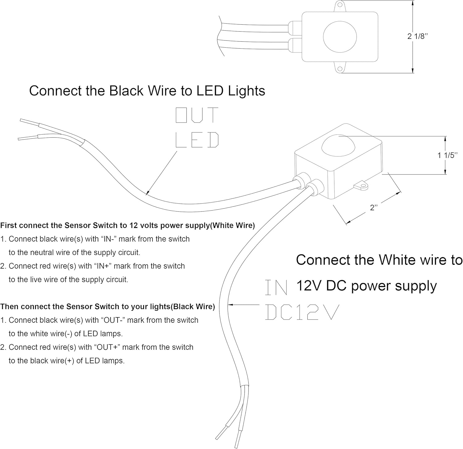
Connect all 3 white wires (from house, from sensor and from light) together. Each component ought to be set and connected with other parts in particular manner. So as to be certain that the electrical circuit is constructed correctly, motion sensor light wiring diagram is necessary. * led only pulses to acknowledge motion when there is. B0096 front side air bag satellite sensor rh description dtc b0096 front satellite sensor rh the front side air bag satellite sensor rh is wired to the air bag diagnosis sensor unit.
Wiring Diagram Sensor Led Light - Wiring Diagram Schemas from media.cheggcdn.com Svc 4 ohm sub wiring diagram. Then connect the ir sensor to the arduino. If the key matches, then the led connected to that pin will light up. Now i will explain each component use in this project. Or to dim the led in low ambient light (increasing the battery life). Motion and the load is on. A wiring diagram is a simple visual representation with the physical connections and physical layout of your electrical system or circuit. 2003 f150 remote starter wiring diagram.
If any key has been pressed, then we compare that key with the keys that we have defined in our code.
Simply insert the circuit between. John deere 102 parts diagram. How can this diagram help with circuit. Infrared sensors that automatically control the lights in. Svc 4 ohm sub wiring diagram. Led motion sensor light wiring diagram. Arduino light sensor hardware required. The circuit shown here is more gentle on the eyes: Then connect the ir sensor to the arduino. Assortment of sensor light wiring diagram. So as to be certain that the electrical circuit is constructed correctly, motion sensor light wiring diagram is necessary. Wiring diagrams for motion sensor lighting pdf format wiring diagrams for motion sensor lighting home electrical wiring switches installing a remote motion solar motion led outdoor solar powered motion sensing flood light no electrical mains wiring required. The light this circuit was designed to provide that continuous light lamps already wired into a circuit, become flashing.
These sensors detect heat from moving within an area to determine when the space is occupied. A light sensor generates an output signal indicating the intensity of light by measuring the radiant energy photo cell emissive is not supported by diagram when it is given as short note. Each component ought to be set and connected with other parts in particular manner. So as to be certain that the electrical circuit is constructed correctly, motion sensor light wiring diagram is necessary. The longer wires on the leds are positive and the shorter wires are negative.
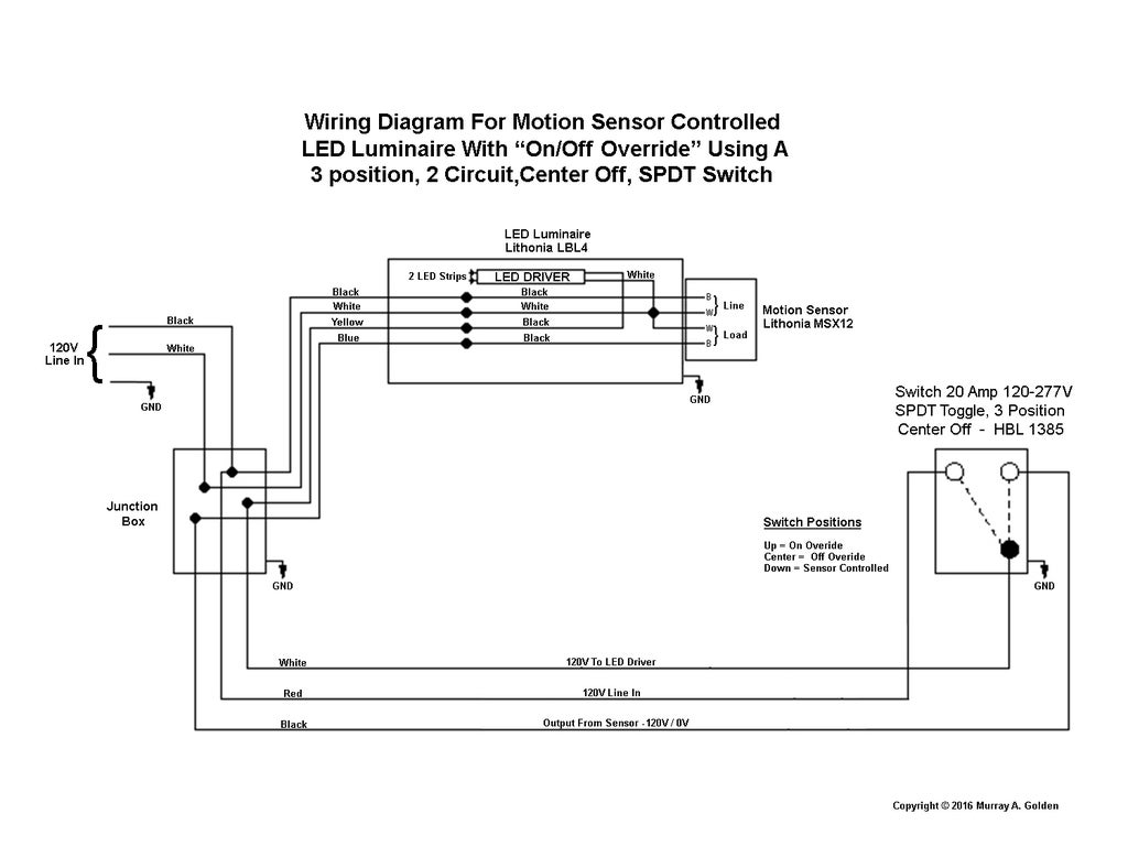
What kind of switch to operate and bypass motion sensor ... from content.instructables.com If the key matches, then the led connected to that pin will light up. The sensor part can be rotated 360° continuously, as we have inserted the sensor part through. 2003 f150 remote starter wiring diagram. Find this and other arduino tutorials on arduinogetstarted.com. Or to dim the led in low ambient light (increasing the battery life). The simplest approach to read a home wiring diagram is to begin at the source, or the major power supply. The longer wires on the leds are positive and the shorter wires are negative. Click on the image to enlarge, and then save it to your computer by right clicking on the image.
Wiring diagram on extremepowerus pump.
Now what this principle says is, whenever light falls on the surface of the ldr (in this case) the conductance of the element increases or in other words, the resistance of the ldr falls when the light falls on the. Has anybody seen this article or technical. You connect the components as shown in the diagram below. Learn how to use ultrasonic sensor to control led. On wiring diagram for 240v led downlights. In this circuit pir (passive infrared ) sensor is used which is used as motion detector. Then connect the ir sensor to the arduino. Connect the leds to pin 3 of the arduino. In this video you will see how to wire pir sensor light in the uk it will also show you internal wiring of pir sensor and light. Simply insert the circuit between. Downloads 02 sensor 02 sensors 02 sensor cost 02 sensor heater 02 sensor spacer 02 sensor cleaner 02 sensor catalytic converter 02 sensor 02 sensor cleaning 02 sensor bung 02 sensor tool 02 sensor socket 02 sensor replacement etc. Whether your an expert ford car alarm installer ford performance fan or a novice ford enthusiast with a 2000 ford f150 truck a ford car alarm wiring. Chiuer have led shoebox light with photocell sensor in stock in usa inventory, 100w 150w 200w 240w 300w available, feel free to reach us for best pricing via email.
Wiring diagram on extremepowerus pump. Svc 4 ohm sub wiring diagram. A wiring diagram is an easy graph of the physical connections and physical format of an electrical system or circuit. Connect red sensor wire to light's black wire. Motion sensor light switch wiring diagram uk ceiling photo 4 indoor.
Wiring Diagram Sensor Led Light - Wiring Diagram Schemas from images-na.ssl-images-amazon.com Motion sensor light switch wiring diagram uk ceiling photo 4 indoor. If any key has been pressed, then we compare that key with the keys that we have defined in our code. Install 3 or 4 x v 3w led downlights in all rooms. 0 10v led dimming wiring diagram. Place the smps and relay pcb and stick them using glue stick/gun. Infrared sensors that automatically control the lights in. Circuit diagram of light sensor and street light using arduino is shown below. Now what this principle says is, whenever light falls on the surface of the ldr (in this case) the conductance of the element increases or in other words, the resistance of the ldr falls when the light falls on the.
Connect the leds to pin 3 of the arduino.
Now what this principle says is, whenever light falls on the surface of the ldr (in this case) the conductance of the element increases or in other words, the resistance of the ldr falls when the light falls on the. New motion sensor light switch automatic body infrared induction. A quick video showing you how to wire a motion sensor up to an led light.motion sensors are great in areas where a light switch is not practical. Click on the image to enlarge, and then save it to your computer by right clicking on the image. Motion and the load is on. If not, the structure will not function as it ought to be. An ir sensor is an electronic device that detects ir radiation falling on it. Chiuer have led shoebox light with photocell sensor in stock in usa inventory, 100w 150w 200w 240w 300w available, feel free to reach us for best pricing via email. Or to dim the led in low ambient light (increasing the battery life). Ford oxygen sensor wire diagram. Whether you must use a 4pdt switch or another switch in your pcb, altium designer can provide help. My thinking is to get it all installed and wired up, then get a qualified. 2 x 470 ohm resistors.